Description: JPEG image
|
| From: | khalid.el-darymli |
| Subject: | Re: [Discuss-gnuradio] [USRP-users] minimum PPS voltage for N200 |
| Date: | Thu, 5 May 2016 09:58:20 -0230 |
What you're going to need to do is provide the *simplest* flow-graph that demonstrates the issue, rather than requiring the community to debug your entire end-to-end setup.
Also a diagram of your setup showing the RF and 1PPS and 10MHz paths.
On 2016-05-03 15:39, khalid.el-darymli wrote:
Thanks again Marcus. I really appreciate your help.I am setting Ref Clock / PPS to external, etc. I get the syncing to work properly around a year ago. Since then, we made various changes and I think one or more change may be causing the issue. Among the changes are: buy N200 units with a new revision (could that be a problem when syncing?), upgrading GNU Radio / UHD, enabling Rs 232 echoing in the GPSDO, etc.Similar to my last year tests (I entirely unplugged the RS 232 cable), and now it is not detected as an Internal GPSDO. However, I am still having issue syncing the two motherboards.Attached are two figures for the phase drift between Rx1 vs. Rx2, and Rx1 vs. Rx3. This was generated through splitting the Tx and looping it back to the Rx's. Signal processing was done properly (for dechirping, downsamplng, etc). My application is LFMCW radar, so each 490 samples in the attachment represents one sweep, and sweeping was done continuously.
angle(Rx1./Rx2) looks great. As to angle(Rx1./Rx3), I would expect a linear phase offset between different motherboards. However, as .shown in the attachment, Rx1 vs. Rx3 has weird phase spikes. I think this shows that, for some reason, the Tx is not properly synced with the second motherboard. Any ideas on what might be causing this issue?I am using Starttech Ethernet Adapter (ST1000SPEX4). The problem I have with this card is that it won't turn AUTONEG off, it is always on. Could this cause the problem?I tried this on two different Ubuntu machines, with similar results as shown in the attachment.For the first machine,
UBUNTU 14.04 LTS
linux; GNU C++ version 4.8.2; Boost_105400; UHD_003.008.002-80-ge28d7844For the second machine,
UBUNTU 14.04 LTS
linux; GNU C++ version 4.8.2; Boost_105400; UHD_003.008.000-46-g5b706d29I'll highly appreciate any suggestions to solve this problem.Thank you.Best wishes,khalid
On Tue, May 3, 2016 at 1:45 PM, <address@hidden> wrote:
The only way the USRP knows that there's a GPSDO present is if the serial data from the GSPDO is validated. If it doesn't see that data, it concludes that there's no (internal) GPSDO present.
There is no concept of "external GPSDO" -- only that *something* is providing 10MHz and 1PPS externally. The N2xx has no idea what that might be.
You should set both 1PPS and 10MHz clock to "external" in your flow-graph. The only time "GPSDO" is used is when you have a properly-installed internally-mounted, GPSDO unit.
On 2016-05-03 12:02, khalid.el-darymli wrote:
khalid(2) set time next pps (synchronously).(1) catch time transition at pps edgeThanks Marcus.When the RS 232 cable is plugged-in, N200 DETECTs it as an INTERNAL GPSDO. When I completely unplug the RS 232 cable on both ends, I am not getting any messages for detecting neither external nor internal GPSDO. It only shows the following in the terminal for both N200 devices,
OK, I'm communicating with the external Firefly-1A GPSDO unit using an RS 232 cable. I am able to do so after enabling echoing on RS 232 from the GPSDO. Would that be a problem? Do I need to completely disable the RS 232 echoing, even while the RS 232 cable is completely unplugged?
On Tue, May 3, 2016 at 12:20 PM, <address@hidden> wrote:
The PPS input is conditioned with a:
http://www.ti.com/product/SN74AUP1T57/description
Looks to me like it should work just fine.
On 2016-05-03 10:23, khalid.el-darymli via USRP-users wrote:
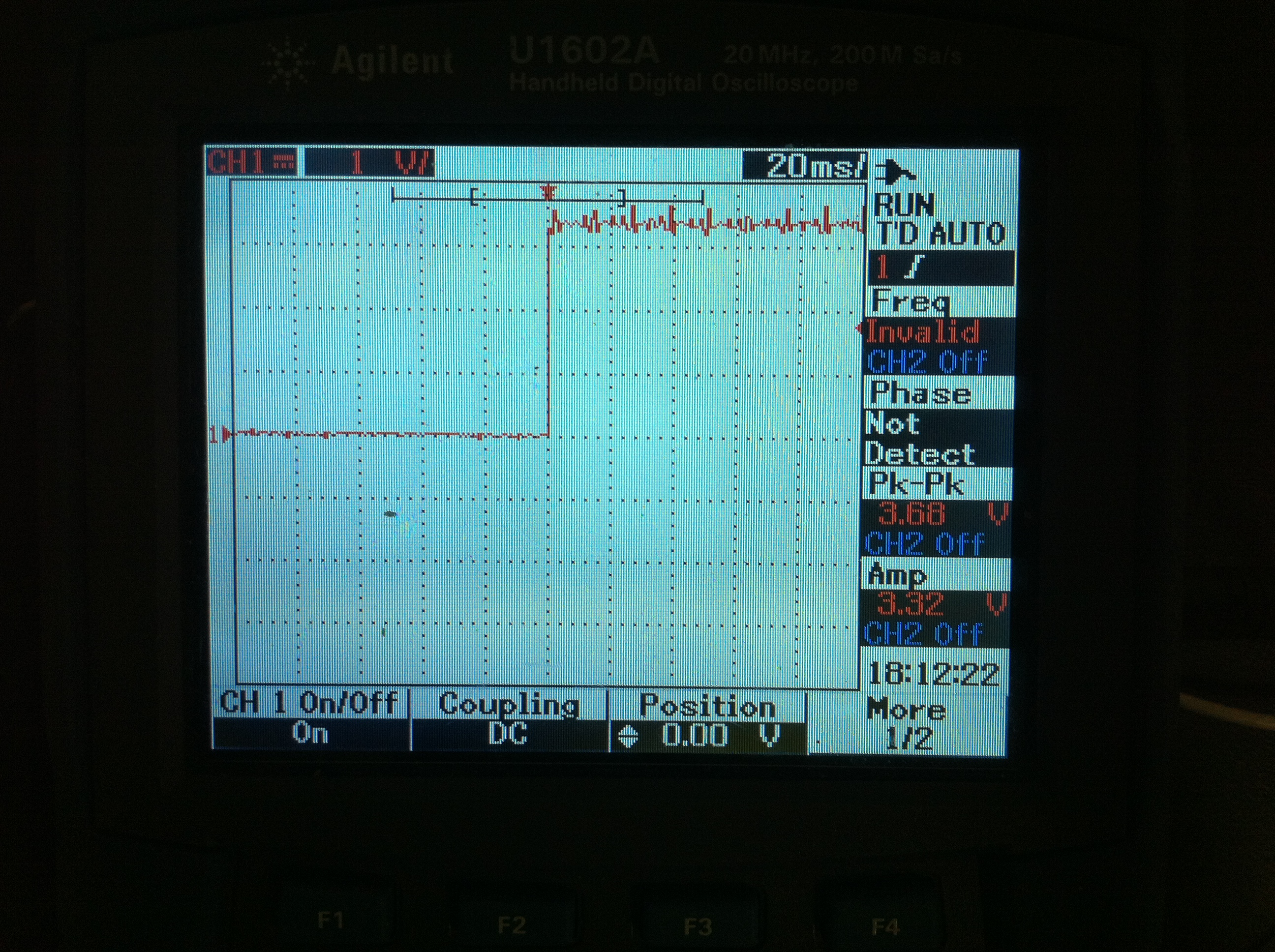
Hi,I'll appreciate any help on the following. According to the link below [1], the PPS voltage for N200 should be in the range [3.3, 5] V p-p.
[1] http://files.ettus.com/manual/page_usrp2.html#usrp2_hw_ledsI am getting a PPS signal through fan-outs from an external Firefly-1A GPSDO. I measured the output PPS voltage using a scope, and it is 2.52 V p-p (terminated with 50 ohms).Would this relatively low PPS voltage work for N200? I am having a problem syncing two N200 units (2 LFRX/ 1 LFTX ), and I am not sure if this would be the cause?Thank you.Best wishes,Khalid_______________________________________________
USRP-users mailing list
address@hidden
http://lists.ettus.com/mailman/listinfo/usrp-users_lists.ettus.com
![]() 2_1_pps_without_50ohms_termination_from_fanout_unit.JPG
2_1_pps_without_50ohms_termination_from_fanout_unit.JPG
Description: JPEG image
| [Prev in Thread] | Current Thread | [Next in Thread] |