I haven't taken a very detailed look at your flowgraph (the symbol rate being 10e6 with a sampling rate of 400kHz seems odd), but:
- 400kHz sampling rate means that the complex baseband you get
out of your USRP represents but 400kHz of bandwidth. Your let's
have a look at your video: With your eyes, you would notice a
difference only if the pulses shifted by let's say
 ; now,
electromagnetic waves in air practically travel at the speed of
light, so the minimum distance you could visually recognize
would be
; now,
electromagnetic waves in air practically travel at the speed of
light, so the minimum distance you could visually recognize
would be  . I'm pretty sure you don't
move your antenna that much! You will need to zoom in much much
closer if you want to be able to see the pulse position vary.
. I'm pretty sure you don't
move your antenna that much! You will need to zoom in much much
closer if you want to be able to see the pulse position vary. - you even throw away the complex phase information (complex to magnitude), halfing the unambiguous bandwidth; that might be O.K., if your TX signal is spectrally symmetrical (which real signals are, but that's only on the TX side). But why do you do this?
- You do the RRC on the real part of the TX signal and on the
Magnitude (
 ) of the RX signal, but that's
typically not OK, because you not only lose the phase, but also
the sign of your signal. You hence lose the SNR-maximizing
property of a pair of RRC filters.
) of the RX signal, but that's
typically not OK, because you not only lose the phase, but also
the sign of your signal. You hence lose the SNR-maximizing
property of a pair of RRC filters. - Your USRP sink and source are not inherently synchronized. You
need to start them at the exact same time; you can do that by
editing the python file GNU Radio companion generates, and
adding:
now = usrp_source0.get_time_now() #or however your source is called
starttime = now + uhd.time_spec(1.5) #1.5 seconds in the future
usrp_sink0.set_start_time(starttime)
To be honest, I think the fact that you didn't notice that your temporal resolution wasn't nearly sufficient is a bit of a bad sign; I sometimes find myself "panicking" about something that doesn't work, and I always found it helpful to then take a moment, sit down, drink a coffee, take a sheet of paper and do some math or drawings or such things to find out what I expect my system to do.
Your radar is a bit odd -- the whole real signal / complex-to-magnitude is a very atypical approach for radar, because range resolution (ie. the smallest distance change you can measure) is proportional to unambiguous bandwidth for pulse radars (and basically, all radar types); so usually, you try to squeeze the maximum bandwidth out of your system and avoid throwing away half of it by only considering real signals!
This also makes your usage of the RRC a bit questionable, but you might have other reasons to use it (shapers for pulse radars are often something like Chebychev windows).
By the way, the theoretical lower limit for a simple one-way pulse radar's range resolution is
 (complex sampling!
  ), which gives us
 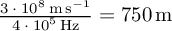 for your case. So
you really need to increase your sampling rate by a factor of at
least 100, if you don't want to run around more than 7.5m.
for your case. So
you really need to increase your sampling rate by a factor of at
least 100, if you don't want to run around more than 7.5m. Best regards,
Marcus
On 07/13/2015 03:56 AM, Manuel David Lozano Amezquita wrote:
Hi everyone,
I have been doing this proyect for a few months but until this moment I don't have idea why it doesn't works, I need to ask to the expert community, mainly to find a line of work.
I would like to measure the distance between two anthenas that are connected to the USRP B210. I'm trasmiting a signal with period of 1kHz but the pulse is just 125 Hz of that period, as I show in the attached image. This signal is trasmitted in a frecuency of 1.8 Ghz.
So, I want to measure the time delay on the Scope Sink, or in Matlab the samples delay that are between the trasmitted signal and the received signal. If I could have this information I could know the distance by the formula v=d/t, where v is the speed of the light, d= distance and t= time delay of the two signals.
When I run the proyect, the time delay doesn't change when I change the distance between both anthenas, as I show in the attached video. I don´t know Why this delay doesn't change, or I don't know if I'm doing something wrong in the receive part.
Then, any help will be very useful.
Kind regards,
Manuel
_______________________________________________
Discuss-gnuradio mailing list
address@hidden
https://lists.gnu.org/mailman/listinfo/discuss-gnuradio