Description: PNG image
|
| From: | Gayathri Ramasubramanian |
| Subject: | Re: [Discuss-gnuradio] GR, USRP, and GPIB measurements |
| Date: | Fri, 22 Aug 2014 00:50:38 -0700 |
Hi

Thank you for previous note.
I removed the FFT block and made my flow graph similar to yours. It works now :)
It is the first time I am working with the QT GUI widgets so kindly help clear the foll doubts.
1. I do not have the QT_FREQUENCY_GUI_SINK BLOCK you have used only the QT_GUI_SINK which gives the frequency spectrum. This is because of the lower version ( 3.6.4.1) I suppose.
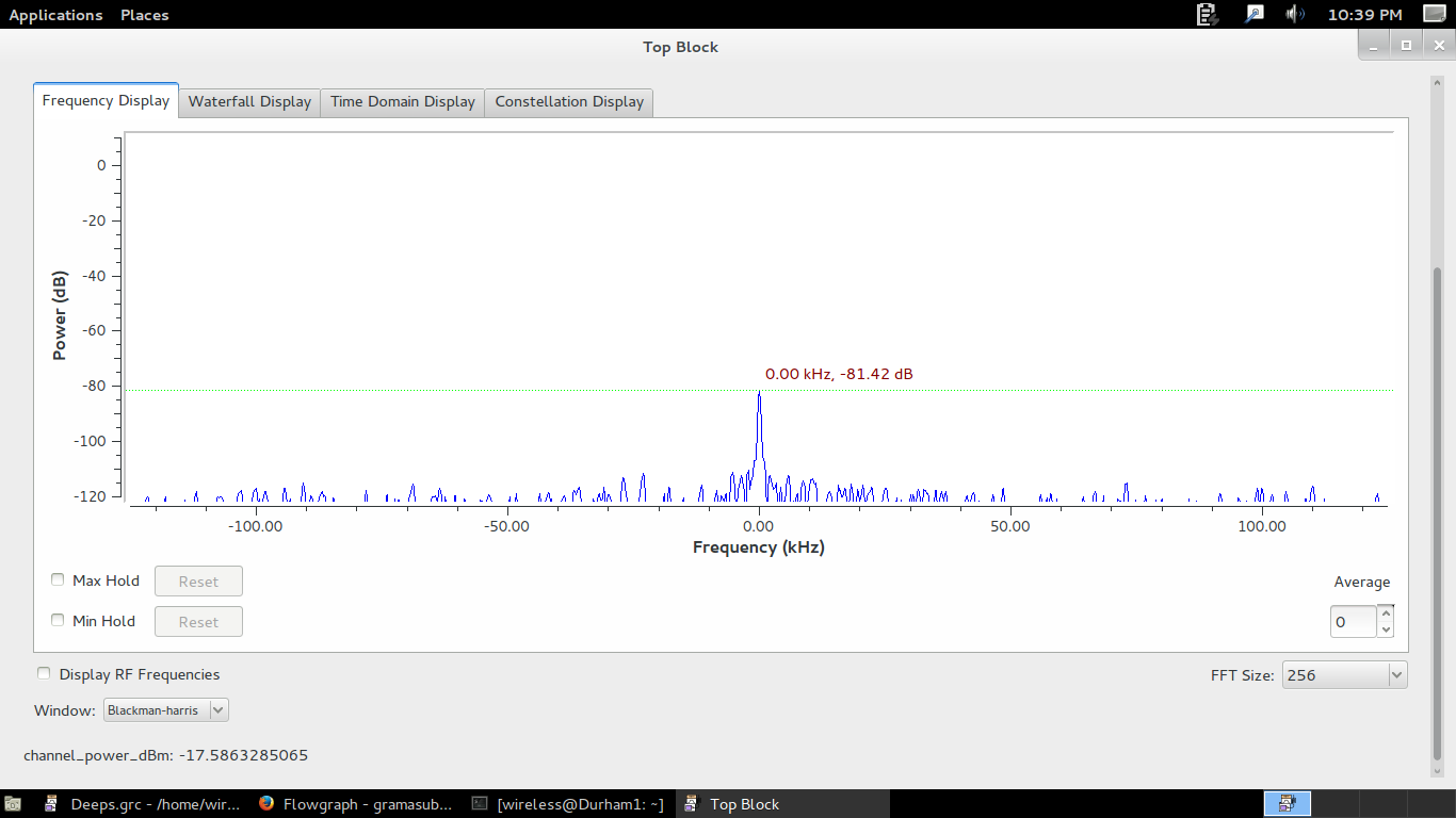
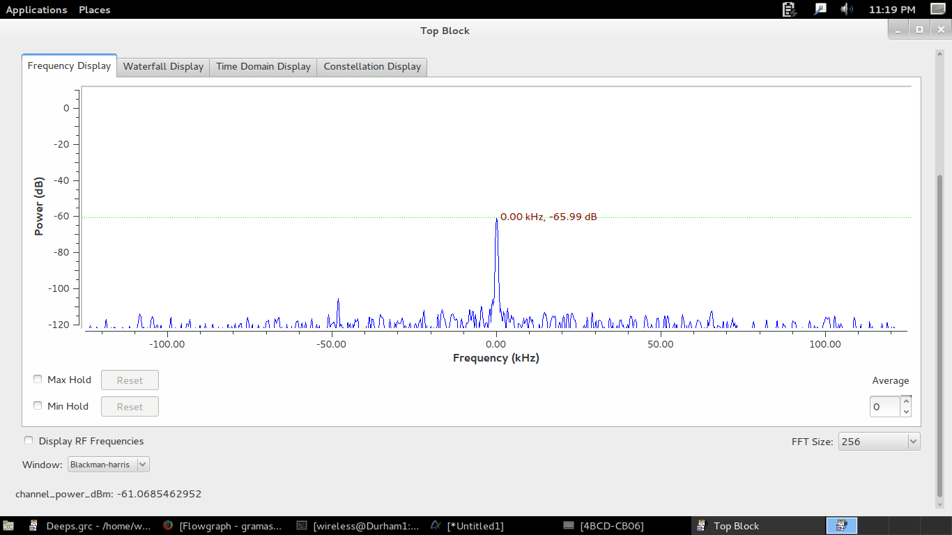
For a USRPN210+WBX board I got the calibration factor to be as follows:
@ 400 MHZ, K = - 62.8
@ 900 MHz ; K = -58.8
@ 1.8 GHz ; K = --52.5
I tested for 3 devices (USRPN210+WBX) and got around same result . The Gain was set to 0. This does not match the value you had obtained with your test.
Is there a major difference in the working b/w QT_Frequency_SINK and QT_GUI_SINK that would affect the final result?If so, Can you suggest a work around. .
2. The channel gain value seems to add to the transmitted power from signal generator. So the calibration factor also needs to have channel gain added to its value for getting same result.
So it seems like the channel gain affects the signal power like a LNA and hence increases the strength of the signal wrt to the noise. Then how is it different from RX gain.? Im a little confused on

where the gain parameters actually impact the value of the signal.
You don't need to take the FFT to get the power. See my attached example (in
GR 3.7). Just take the output from the USRP, complex_to_mag_squared,
integration with decimation to 1 Hz, 10*log10() + k, and probe at 1 Hz rate.
I'm using an N210 + WBX with gain=15 dB. That gives me a calibration factor
of k=-34.8 dB. I can vary power of my signal generator from -50 dBm to -10
dBm with less that 0.1 dB error in the calculated power.
https://dl.dropboxusercontent.com/u/49570443/power_calc.grc
https://dl.dropboxusercontent.com/u/49570443/power_calc.grc.png
Thanks,
Lou
KD4HSO
<http://gnuradio.4.n7.nabble.com/file/n49981/power_calc.png>
Gayathri Ramasubramanian wrote
--> Hi
>
> Thank you for your note.
>
> I am trying to get the power of received signal using the blocks you had
> suggested previously.
> I have attached a flow graph snapshot ('uhd_fft_DK.grc.png").
>
> I am using the UHD:USRP Source to receive the signal which in turn sends
> the signal in the foll path
> "complex to Mag^2" block --> "integrate and decimate" block --> "10 log
> +k" block---> "signal probe" block.
>
> However there are errors mainly referring to the in-compatible I/O sizes
> of
> source (complex to Mag ^2 block) and sink (Integrate and Decimate block).
>
> The I/O size of "Complex_Mag^2" block is said to be 4096, while the I/p
> size of i"ntegrate and decimate" block is 4. ==> error as not compatible.
> Should I change the Vector length? I am not quite sure?
> The error propagates to other blocks if I change anything.
>
> Kindly help solve this.
>
> I have also attached another flowgraph (flowgraph screenshot.png) which
> works but it doesn't have the "integrate and Decimate" block or the
> Log10+K
> block but it works and receives the signal (developed by someone else
> previously in our lab). Now since the "Log10+K" block is missing, does it
> mean the output is given in mwatts instead of dBm?
> I cant seem to use this version on as the "probe_signal_vector" block does
> not seem to be supported in GRC 3.6.4.1 which is the version in my system.
>
> I tried using simple probe_signal block instead but again faced the I/o
> size incompatibility error? Is there a work around for this "probe signal
> vector" block?
>
> Also could you explain briefly how to approach and solve there I/o size
> errors.
>
> Look forward to your response
>
> Thanks
> Gayathri
View this message in context: http://gnuradio.4.n7.nabble.com/GR-USRP-and-GPIB-measurements-tp49727p49981.html
Sent from the GnuRadio mailing list archive at Nabble.com.
_______________________________________________
Discuss-gnuradio mailing list
address@hidden
https://lists.gnu.org/mailman/listinfo/discuss-gnuradio
![]() Screenshot from 2014-08-21 22_39_57.png
Screenshot from 2014-08-21 22_39_57.png
Description: PNG image
![]() Screenshot from 2014-08-21 23_19_53.png
Screenshot from 2014-08-21 23_19_53.png
Description: PNG image
| [Prev in Thread] | Current Thread | [Next in Thread] |