[Top][All Lists]
[Date Prev][Date Next][Thread Prev][Thread Next][Date Index][Thread Index]
[Discuss-gnuradio] Getting strange outputs from FLL_Band_Edge block
|
From: |
Nazmul Islam |
|
Subject: |
[Discuss-gnuradio] Getting strange outputs from FLL_Band_Edge block |
|
Date: |
Mon, 18 Jun 2012 23:31:52 -0400 |
I am trying to implement a PN_correlator through gnuradio-companion generated python codes. I am transmitting a continuous stream of repeated GLFSR source and I want my receiver to be synchronized (as much as possible) with the transmitter. I have followed the generic_mod_demod.py in designing the transmitter and the receiver and I have used the following paths:
Tx: GLFSR source (producing +1 & -1) --> RRC --> USRP Sink
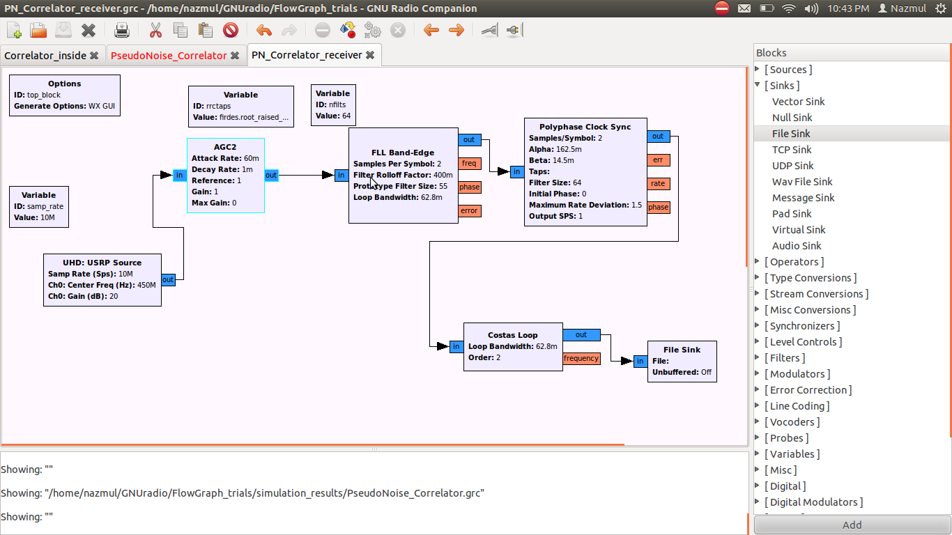
Rx: USRP Source --> AGC2 --> FLL Band Edge --> Polyphase Clock Sync --> Costas --> File Sink (the receiver snapshot is attached as PN_receiver.png).
I have the following issues:
1. When I run the Rx without FLL, the USRP sink spits out roughly 40 MB data by 1 second with 10M sample rate. However, if I run the Rx with FLL, the USRP spits out much lower amount of data, e.g., 4 - 6 MB within 1 second. I think that Josh investigated a similar issue before (
http://lists.gnu.org/archive/html/discuss-gnuradio/2011-11/msg00080.html). Can this strange phenomenon have an adverse effect in the output?
2. More worryingly, I am getting strange outputs from FLL. I will be a bit verbose in explaining its weird nature and I am sorry for that. I am transmitting a PN sequence with 1023 chips. The theory is simple: if I correlate the Rx output with the PN sequence, I should get a high peak after every 1023 symbols and almost zero in between.
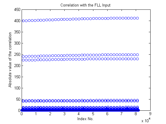
--- The "Correlation_FLL_input.png" shows the correlation between the AGC2 output and PN sequence. At this point, I have 2 sample/symbol. The high value (~ 400) suggests that one sample fell close to the symbol peaks. The medium values (~ 200) denote that the other sample fell midway between two symbol peaks. Fair enough.
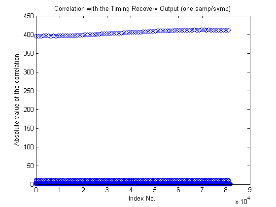
-- If I take out the FLL_Band_Edge block (i.e. AGC2 --> Polyphase_Clock) and take correlation after Polyphase_Clock_Recovery, the output takes the form of "Corr_timing_recovery_without_FLL.png". High peaks after every 1023 symbol & almost zero correlation in between, great!
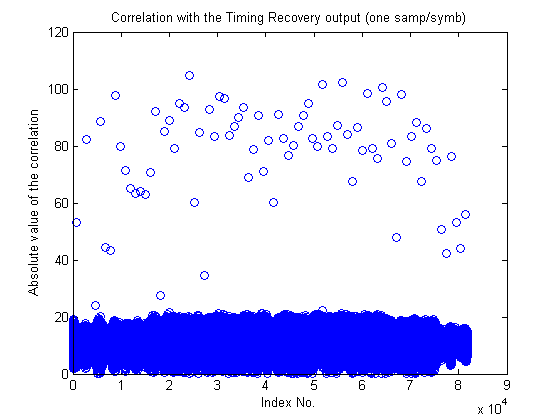
-- If I keep the FLL block, the correlation after FLL_Band_Edge + Polyphase_Clk_Recovery takes the form of "Corr_timing_recovery_with_FLL.png". You can see that it is completely smeared and there is no pattern at all! I took the correlation after FLL and found that the strange output is due to the FLL block, not timing recovery.
Am I doing any gross mistake with the FLL_Band_Edge parameters? I pretty much took the parameters from generic_mod_demod.py and they are also aligned with the RRC of the Tx side.
3. Does GNUradio have any other FLL block that I can test?
Suggestion on any of the questions will be appreciated. Thanks a lot for reading my long email :S
Nazmul
--
Muhammad Nazmul Islam
Graduate Student
Electrical & Computer Engineering
Wireless Information & Networking Laboratory
Rutgers, USA.
 PN_receiver.png
Description: PNG image
Correlation_FLL_input.png
Description: PNG image
Corr_timing_recovery_With_FLL.png
Description: PNG image
Corr_Timing_Recovery_Without_FLL.png
Description: PNG image
- [Discuss-gnuradio] Getting strange outputs from FLL_Band_Edge block,
Nazmul Islam <=